Connector and Signal Standards for Stereoscopic Display Hardware
Connector Specification:
The standard defines a 3 pin connector for the purpose of providing power and stereoscopic polarity to an external device (LCS glasses, polarising shutter, video demultiplexer, etc).
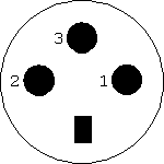
The defined connector is a 3-pin mini-DIN connector (pin assignments are shown in the diagram below):

3-pin mini-DIN socket (front face)
Pin 1: +5VDC
Pin 2: Ground
Pin 3: Stereoscopic Sync Signal
The female connector (socket) is intended to be used on the host controller and the male connector (plug) is intended to be used on the stereoscopic hardware.
Signal Specifications:
![]() Stereo Sync Signal: (1) Standard TTL levels (5V and 0V). Logic 1 state (high) is valid when the signal level is higher than 2.4V and Logic 0 state (low) is valid when the signal level is lower than 0.8V. (2) The host shall not be required to sink more than 10mA in the Logic 0 state nor source more than 0.5mA in the Logic 1 state. (3) Logic 1 state corresponds to the display of the left-eye image and Logic 0 state corresponds to the display of the right-eye image. (4) The signal shall be a square wave with a nominal duty cycle of 50%. The transition from state to state shall occur within 3 horizontal lines of the start of the vertical sync pulse (but not before the start of vertical blanking).
Stereo Sync Signal: (1) Standard TTL levels (5V and 0V). Logic 1 state (high) is valid when the signal level is higher than 2.4V and Logic 0 state (low) is valid when the signal level is lower than 0.8V. (2) The host shall not be required to sink more than 10mA in the Logic 0 state nor source more than 0.5mA in the Logic 1 state. (3) Logic 1 state corresponds to the display of the left-eye image and Logic 0 state corresponds to the display of the right-eye image. (4) The signal shall be a square wave with a nominal duty cycle of 50%. The transition from state to state shall occur within 3 horizontal lines of the start of the vertical sync pulse (but not before the start of vertical blanking).
![]() Power: (1) +5Vdc (+/- 10%). (2) The host must be able to provide 300mA and limited to no more than 1A.
Power: (1) +5Vdc (+/- 10%). (2) The host must be able to provide 300mA and limited to no more than 1A.
The complete standard "Connector and Signal Standards for Stereoscopic Display Hardware" can be obtained from VESA:
The Video Electronics Standards Association, 2150 North First St, Suite 440, San Jose, CA, USA. Ph:408 435 0333 Fax:408 435 8225 http://www.vesa.org
The VESA standard was compiled by Bob Myers (Hewlett-Packard Co.) with contributions from Dave Milici (StereoGraphics), Richard DeHoff (NuVision), David Qualman (NuVision), Greg Marshall (Canopus), Greg Hamlin (VRex), Anders Frisk (Fujitsu ICL), Tom Ryan (SciTech Software), Alain d'Hautecourt (Viewsonic), Hans van der Ven (Panasonic), and Jack Hosek (NEC Technologies).
